Friday, December 25, 2009

A Christmas present for my wife…

I don’t often have personal posts on my blog, but with the two little girls, being busy at work, etc (I know we are ALL busy this time of year) I wasn’t able to get everything I wanted for my wife.

So, right about now we are waking up and making our way down the stairs with the girls. It’s a first Christmas for one and the first that the other will really remember.

What my wife doesn’t know is that in addition to the presents under our tree and in her stocking, she has one more big gift.

And that’s the purpose of this post. The only thing she has to do know is choose one from all the great suggestions she has put out there for the past month…

Will it be the bedroom furniture set? The living room furniture? (I see a theme…) The flat screen TV? Or the… dare I say it… the mini-van?

She doesn’t know I’m writing this, but she does subscribe. My prediction is, when she sees this on her radar, she will think it is a big joke… Well, that’s why it’s HERE, out where EVERYONE can see. I want her to know that this is better than your everyday IOU. I’m sure one of my “Loyal Readers” will hold me accountable…

Stay tuned to see what she chooses. (I'm wishing Flat screen, but I'm thinking a van... you know the one with cool remote open/close doors, the DVD and the convertible seats? Yeah, THAT one...)

Meet the 2009 Routan APR Special.

0% APR* for 72 months.

Merry Christmas to all, and all a Good night.

Sunday, December 20, 2009

Happy Holidays... I think.

Rather than compose my own politically correct, religiously neutral, legally viable, and morally responsible Holiday Greeting, I will just link to the all encompassing greeting at REVIT Structure Learning Curve.

Happy Holidays All!! Even you CAD users out there...

Saturday, December 19, 2009

Santa is a Reviteer?....

The general Revit population, must have been good boys and girls this year. Check out this link to a special Christmas Eve gift from Arch in 3D.

Happy Holidays and Peace on Earth.

Friday, December 11, 2009

AU 2009 Classes available online…

At least according to the email I recently got from AU. I haven’t double checked, but here is the link if you want to see for yourself.

AU 2009


Yep they are there... Just checked.

Wednesday, December 9, 2009

Autodesk Design Review Usage and Features Prioritization Survey

Take the 10 mins and give your feedback on Design Review.  This is your chance to influence which way the product develops and help ADSK understand who uses the product and how they are using it.

Can’t hurt, might help.

Link to Survey

Monday, December 7, 2009

AU afterglow… aftermath…

I suppose it depends on your viewpoint, but no matter who you are, another AU is in the bag…  While I haven’t heard any hard numbers yet, the estimates I heard run from 5900-6800, but I think that those are all hearsay.  Even as a newcomer, I can tell that it had been scaled back.  From stories of hotel suites with sunken living rooms and free top-shelf booze last year to the reality of this year’s standard King or Double rooms and no “hard stuff” at all at the exhibit hall or parties.  Add to that the “technical difficulties” the sound tech was having during the string concert at the AU Bash and the slightly (ok, seriously) cheesy Karaoke, and you have a formula for some disappointed AU-ers.  That said, in this down economy I think Autodesk did a wonderful job.  I think they kept quality classes and a reasonable price.

As far as I’m concerned, I thought the whole event was great.  I feel so lucky to have been able to meet some of the hardest hitters in the industry face-to-face in an environment of sharing and collaboration.  Isn’t that the point?  Folks at AU freely share content, templates, ideas, processes, etc.  It’s so exciting to be part of our industry right now. 

I don’t think it was the glitz and glam of Vegas (it has more to do with the weekend spent with my family after the fact) but I am re-charged and re-energized by great conversations and information exchange with awesome people.  The weather over the next few days looks promising for a couple of in-depth blog posts. Gotta love blizzards!!!

Thursday, December 3, 2009

AU 2009 Day 3 Part 2

While I have been a fan of his blog for awhile, I didn’t expect the sheer amount of personality that David Butts posses (as was evidenced by his Gold 2010 shaped glasses, his Mardi Gras bead prizes for audience participation.)

In his class MP314-1 Revit MEP Powerful tips and tricks is a must watch for anyone in the beginning to intermediate stages of using Revit MEP.  When this is posted online be sure to watch and download the accompanying material.

Bonus: He usually posts a Kick @SS MEP Systems Project template to the class site that will go a long way towards helping you create an office standard template.

Also, check out his new instructional books for Revit MEP Basic and Advanced

AU 2009 Day 3

One thing I didn’t expect (I probably should have) is that having all of this dialog with other users and managers involved in the BIM/VDC/IPD process has given me NUMEROUS ideas for future blog posts.  I HAVE been taking notes and hopefully I will be able to get these ideas out here for everyone to share in the upcoming weeks.

One of the stand out sessions (for me anyway) from yesterday was put on by Joshua Kanner from Vela Systems, INC I posted about VELA a few months ago, and I was very excited to see the product a little closer and be able to have a conversation with Joshua in the exhibit hall after hours.

What a neat tool.  It allows your field personnel to interact with the BIM using a very friendly interface (one that is probably not far removed from what they use now, even if they are using hard-copy forms) that is task/process based. An example would be the staff commissioning the facility can use a barcode (or even RFID) scanner to track equipment (Received, damaged, ready to install, installed, prepped for functional test, etc) using a simple procedure that is familiar to them.  The barcode/RFID tag can add data directly from the Vela database when scanned.  That data (manufacturer, model, whatever the supplier decides to add) can then be automatically added back into the NavisWorks model the GC is working in.  Read that again… Automatic bi-directional information transfer.  WE ARE THERE!!!!   This IS BIM!!!!!  The sky is the limit.  Color code views to show equipment status (delivered, damaged, etc)  Pan back and see your major pinch points visually. 

Can you tell I’m excited?  Geesh….

Thought  provoking idea of the day:

How can I use the model to not only maintain my building, but control it as well?  With automatic control and sensing systems out there, are we really that far away from this?

Wednesday, December 2, 2009

Still Alive and Well in AU

Contrary to what my wife may think, I AM alive and doing well here in the vast Nevada desert.


Today is shaping up to be quite busy and full of information, but I wanted to take a moment and give some quick props to Laura Handler (Tocci Building Corp) and David Epps (Holder Construction) for there presentation of the different ways Contractors can arrive at a BIM. They talked about the pros and cons of doing 2D conversions in house, outsourcing the creation of the model and receiving the model directly from the designer. Very well done and worth checking out at AU online when available. CR118-1 (I will provide a link when it becomes available on AU Online.) Be sure to check out Laura's Blog for more about using BIM from a contractor's point-of-view.


I'd also like to congratulate Heapy Engineering of Dayton Ohio for having an Upper Management that totally "gets" what BIM, VDC and IPD are all about. They are technologically savvy and looking to stay on the forefront of the industry even in a down economy (rumor has it they may even be hiring, unheard of right now.). They understand (at every level in the organization, it would seem) that VDC/BIM is not a software implementation , but rather, a complete reorganization of the current project delivery process. Using the new BIM authoring tools (namely Revit) to deliver the same old deliverables with the same tired process is a recipe for disaster. Their successes should serve as an inspiration to anyone making their first steps down the road to BIM and integration. Check out their class MP122-2 (link to come.)

Tuesday, December 1, 2009

Alive and well in Vegas...

Touched down around Noon yesterday and had a pretty laid-back afternoon. Took in the "daytime" Strip (the place is so over-the-top,) watched part of a disappointing football game (C'mon Pats, you're killin' me) and checked out the AEC Mixer.

Somehow I missed the invite to the Blogger mixer, heck I didn't even know there was one. Ah well, guess that's what I get for not posting much in the days and weeks leading up to AU.

Looking forward to awesome day of classes and meeting some of my blog-o-sphere friends and acquaintances.

More to come...

Monday, November 23, 2009

AU's a comin'....

I'm a goin'. Are you? I hope so.

Although attendance is projected to be down considerably from last year, it looks to shaping up to a great event.

This will be my first time attending, and I am open invitations to share an adult beverage of choice and shoot the .... Revit.

And contrary to popular belief, I'm pretty sure when it's your first time that the rounds not on YOU, but on everyone else. But, I've been wrong before. ;)

Monday, November 16, 2009

Revit X- files

Mechanical and Electrical Reflected Ceiling Plan (RCP) Strangeness

There is a strange behavior, when a RCP’s Discipline parameter is set to either Mechanical or Electrical, that has caused a problem for us on a couple of occasions.

Normally the view parameter Underlay Orientation is grayed out and not available when there is no Underlay selected. However, when a view (any view) is set to Mechanical or Electrical, that parameter becomes active and can be changed. This hasn’t caused a problem with floor plans yet. But I see how it could.

RCP_strangeness

While it’s bad enough that a user could change this parameter to plan in a RCP (or to RCP in plan even) what makes this truly sinister is that the default for a NEW REFLECTED CEILING PLAN is PLAN for this parameter (that’s why it hasn’t caused issues for plans, it’s the default there as well.)

We have had occasions where the ceiling just no longer shows (as expected when set to plan) or in a linked model it was just showing the ceiling grid in the wrong place. Which is far worse, as we found when we went to coordinate light fixtures, air terminals and ceilings. YIKES!!!!!

So, it’s imperative that anyone who makes a new ceiling plan that is to be used for one of these disciplines needs to change that parameter to read Reflected Ceiling Plan.

To make matters more difficult, Revit has decided that this parameter is not something that you would want to set as part of a view template, even though you can set it’s Underlay (hmmmmm, that makes sense. I can’t count the times I’ve wanted to have multiple view have the same Underlay. Well only because it hasn’t happened.)

RPC_inconvience

And to really confuse the user, when the same view (with the incorrect value for Underlay Orientation) is set to COORDINATION or ARCHITECTURAL for it’s Discipline… of course it displays correctly (exactly as you expected, right?) Now, don’t be silly and think that it has somehow magically changed the incorrect value. No, Revit has just decided to ignore it.'

RCP_madness

Have I logged this as a support request? No. I probably should, but I’ve been busy fixing my own issues…

Wednesday, November 11, 2009

All aboard the Boolean Express

Today's post is by a guest blogger. Eric Shappe is a BIM Content Administrator in our office. A Revit Family Guru. He's going to take us on a journey on the Boolean Express.

We have lots of fun with conditional statements in our office. There's no "ifs, ands, or buts but there are plenty of IFs, ANDs, or NOTs.

We have done a lot of experimenting with using YES/NO parameters (Check Boxes) to drive length and visibility parameters. We use IF statements to change multiple aspects of display and size in several of our families.

In this case, the plan was to have a TEXT parameter report one of THREE conditions. Reporting TWO conditions is elementary. I have to hand it to Eric, three was a real challenge.

So yesterday I was trying to figure out how to get glazing in a door to be either “clear”, “wire” or, and here is the kicker “n/a” (or - - as I used). Before I explain how I finally accomplished this I will give you a little background on my existing conditions. First I have a door family which has a nested door panel family inside of it. This door panel has a void that is controlled by 4 yes/no parameters that describe how to cut the door panel and to what dimensions. These 4 yes/no parameters are as follows:

HALF LITE

FULL LITE

8" X 33" LITE

3" X 33" LITE

Then I had created another yes/no parameter that controlled the glazing type from “CLEAR” to “WIRE” named

DOOR WIRE GLASS

Now onto the fun stuff, my first pass at getting this equation to work only yielded two results which were “WIRE” and “CLEAR”. Now that would be fine and dandy if all my doors had some sort of glazing in them, but that isn’t the case. So at first I tried to wrestle with some conditional terms, which basically brought the BIM studio to a screeching halt trying to figure out how to do this. But after an evening to myself and 4 other people trying to take a walk around conditional statement park, our brains had been mugged of any more ideas. All we had ended up with was the following

if(and(DOOR WIRE GLASS, or(HALF LITE, or(FULL LITE, or(3" X 33" LITE, or(8" X 33" LITE))))), "WIRE", “CLEAR”)

As I was driving home trying to parse through this issue it dawned on me, why not just create another parameter driven by each of the glazing parameters, which would give me another yes/no value.

So the next morning I created a WIRE GLASS parameter (pardon the confusing names of some of these parameters) which reads as follows:

if(HALF LITE, "CLEAR", if(FULL LITE, "CLEAR", if(8" X 33" LITE, "CLEAR", if(3" X 33" LITE, "CLEAR", "--"))))

This is basically saying if I have any of the “LITE” parameters checked read “CLEAR” if not then give me “- -“ . Now I had to marry this with my earlier conditional statement that controlled “WIRE” or “CLEAR” which ended up changing to this:

if(and(DOOR WIRE GLASS, or(HALF LITE, or(FULL LITE, or(3" X 33" LITE, or(8" X 33" LITE))))), "WIRE", WIRE GLASS)

This states if both the “WIRE” and any one of the “LITE” parameters are satisfied give me “WIRE” if not then check with the other WIRE GLASS parameter which reads out CLEAR if we have glazing with no wire or “ - -“ which would be no glazing at all.

So in the end I have this: (both are text parameters)

DOOR GLAZING TYPE = if(and(DOOR WIRE GLASS, or(HALF LITE, or(FULL LITE, or(3" X 33" LITE, or(8" X 33" LITE))))), "WIRE", WIRE GLASS)

WIRE GLASS = if(HALF LITE, "CLEAR", if(FULL LITE, "CLEAR", if(8" X 33" LITE, "CLEAR", if(3" X 33" LITE, "CLEAR", "--"))))

Which gives me my 3 conditions WIRE, CLEAR and - -

Enjoy!

Thursday, October 8, 2009

C,c,c... What begins with C?

Columns, ceilings, calculated values all begin with C. (If you don't get the title reference I'm sorry. You must have lead a very deprived childhood.)

After many months of pounding the dangling "C" key on my trusty laptop (lets just say that laptops and small dogs don't mix)I have finally replaced the whole keyboard. Thank you EBAY! and thank you Dell for making a laptop keyboard so easy to replace.

If you under-appreciate the letter "C" (as I have for years) just try to write anything intelligent about Ceilings, or CalCulations, or ConCrete, or even just CAD without one.

While not as important as RSTLN & E (nod to Wheel-of-Fortune fans everywhere) "C" has a special place in our hearts (coronary) and minds (cerebrum, cerebellum.)

While this new outlook on a lowly consonant (or should I say a new way of "Seeing?") may not get me to blog more often (although it surely can't hurt) all the recent correspondence I have received in relation and regards to my Blog will.

BTW, if you haven't received a response yet, please hold out just a little longer. See I just got a new keyboard and...

Friday, September 18, 2009

Design in the Cloud? BIM software as a service?

It's Alive in the Labs posted a link to Project Twitch today. Here you can us Revit, Inventor, or AutoCAD without installing it. What? It's called Cloud Computing or Software as a Service and software (in some sectors) is moving to this model.


The advantages are that you can access the application from anywhere (limited to 1000 mi from the server in this preview) and not just at your desktop and the system requirements should be less. Be sure to read about the other limitations of this technology preview. No saving or uploading your files. This isn't for production, it's for "fun."


Given court rulings such as Vernor v. Autodesk, I wouldn't be surprised if ALL Autodesk software eventually moves to a similar model. With a delivery method similar to this ADSK could shut off the service (just like the power company) if you didn't pay your bill or didn't use the product according to your agreement. I think it would also cut down on pirated software, since you would need access to their server to run the software at all.


Could this be the next iteration of Subscription? Hmmmmmm

Friday, September 11, 2009

In Remembrance- 9/11/2001


Never Forget...
All gave some, and Some gave all.


In Remembrance of the 2700+...

Tuesday, September 1, 2009

"If you don't like change, you're going to like irrelevance even less."

I don't know what was the context for the above quote from General Eric Shinseki, Chief of Staff, U.S. Army, but I think it sums up the BIM movement very well.

This comes from an article posted over on Revit 3D.com

You an also jumped directly to the article. Please read this if you want to know what BIM can do for you and why you need to be thinking about a new way of deliverying information to the players involved in your projects.

Thursday, August 13, 2009

AU 2009 Early Registration

Early Registration for AU 2009 started yesterday at around 8:00 am CT ( at least that's when the first folks in our office were able to get in the system.) If you are planning in early registration then get in soon as classes are filling.

Good Luck and see you there!!!!

Tuesday, August 11, 2009

My OTHER Favorite...


(Credit where credit's due: I wish I knew where this came from, but it's been a round the block at least once)

Monday, August 10, 2009

My all-time Favorite Revit Error

I got this error opening a file. It's short, to the point and has limited options. I love it!!!

Sunday, August 9, 2009

Autodesk and Vela Systems = BIM for the Feild

Autodesk has recently announced that they will be collaborating with Vela Systems to bring a more integrated use of BIM to the jobsite.


By linking Vela's RFID (Radio Frequency Identification) material tracking, BIM on tablet computers and Autodesk's Navisworks model, Field personel can track and report the status of materials and help others visualize the progress of the project.


Read more here.

Thursday, July 30, 2009

Classic UI in Revit 2010

From a coworker's email:
Well - it's happened... Classic UI in Revit 2010!

http://usa.autodesk.com/adsk/servlet/ps/dl/item?siteID=123112&id=13126336&linkID=9243099

I have mixed feelings, but none the less - it's out there now.
More to come I'm sure...

Sunday, July 26, 2009

Adding a new parameter to your family...

Cheesey yes, but the lack of sleep and joy of a new baby often combine, with the effect being cheese...


My family's newest parameter...


Values:
Length= 20"
Weight= 7lbs 8oz
Personality= Sleepy

Tuesday, July 21, 2009

Revit and MAC....?

What is this world coming to?

Check out what the Revit Clinic has to say.

What is this world coming to...? I would say it's coming to a point of REAL Collaboration.

Thursday, July 16, 2009

Revit and the new Janesville, WI Hospital and Clinic

One of our big projects just signed a contract for construction.

St. Mary’s  Janesville Hospital and Dean Health System Clinic in Janesville Wisconsin. 

From a October, 2008 Press Release:

“Dean Health System and SSM Health Care of Wisconsin also announced today that Erdman, a Cogdell Spencer Company, in a joint venture with Shepley Bulfinch of Boston and J.P. Cullen & Sons, Inc. of Janesville, has been chosen to design and construct its new $140 million hospital and physician office campus in Janesville.”

After some delays, we are excited make a concentrated effort to deliver the Dean Health System Clinic portion of this project using Revit.

Here is a link to a promotional video from St. Mary’s Hospital

Wednesday, July 8, 2009

Is Revit faster than…

I’m SO tired of the questions/observations/comments on the speed of Revit in delivering a project. Is Revit faster than <insert drafting software here> (AutoCAD, AutoCAD Architecture, etc., etc.?) I thought Revit was supposed to be faster than CAD… It takes forever to <insert modeling task here> compared to CAD.

Seriously? Which is faster?

This?

World's Fastest Jet

Or this?

World's Fastest Hard Drive

Don’t get the connection? Me neither.

Both of the items pictured are (debatably) the fastest at what the do.

How fast does a SR-71 Blackbird transfer data? Depends on how far away the transfer points are and how much and what is the format of the data.

How fast does a Seagate Savvio 15K drive fly? Depends on who throws it.

Revit and CAD are as similar as a Super Sonic Jet and a Hyper-fast Hard drive. They do (or produce) different things.

Let’s compare apples to apples, or at least to fruit to fruit.

First on the individual “task” level.

Ex: Placing a wall in Revit vs drawing a wall in CAD.

Now I would argue that it actually IS faster for me to model a wall in Revit than it is for someone to draw to lines and a place hatch pattern in AutoCAD (maybe you could keep up if you had a tool that placed all that at the same time, hmmmmmmm, isn’t that AutoCAD Architecture (I won’t go there.)) But let’s just say for arguments sake, that it WAS faster in CAD (a stretch I know.)

OK, now show me an elevation of that wall.

Revit: DONE!

CAD: Draw rectangle>fill with hatch>DONE! (HA, not so bad.)

How about a section?

Revit: Click, Click>Done.

CAD: Rectangle, Fill with hatch (Sounds familiar.)

OK,OK. Now a building made out of those walls. Keep it simple. Single story, flat roof, “office park” building.

Time Elapse, everyone’s done.

Doors.

Revit: Select type>place>place>place>etc., etc.

CAD: Place block (even a “smart” block)>Trim wall>Trim Wall>Repeat.

Wait, move that last door 6”?

Revit: Sure. Move.

CAD: You bet. Move>Trim>Extend>Fix Hatch

Ummmm, 10’ walls won’t cut it, change them to 12’.

Revit: Change elevation of Top Constraint level.

CAD: Redraw 4 elevations (for a box shaped building) oh wait, almost forgot the section.

You know it would be great if I could see that in an Isometric.

Revit: No problem. Click

CAD: Why? We never did that before… I mean, sure. Give me a couple of minutes.

You know, it looks kinda dumpy with that flat roof, how about a simple Hip?

Revit: Got it, like this? Sketch 4 lines>Define Slope>Finish (Section, infinite elevations, 3d/ISOs) Done

CAD: Umm, yeah, I just gotta get the is ISO done. Then I can update all the elevations, the sections, oh geesh and that ISO. Come back tomorrow? (Faster huh?)

Could you guys do an energy analysis on that?

Revit: My Mech tech an export that to Ecotect or Green Building Studio and get you something in a few minutes.

CAD: Ehhh? on… lines…? Hmmm, Ummmm…. What the heck is that Revit guy doing over there? Walkthrough? What? C’mon…

Ok,OK, enough of this. The point is, if you are using CAD to produce Construction Documents and you want to replace drafting with 3D modeling in Revit CAD may (debatably) be faster.

If you want a tool that allows you to investigate and communicate design intent (sometimes, with an Ace user,) in real time. If you want a tool that you can then leverage that model to do energy analysis, Sustainability analysis (based on materials in the model,) Visual and Location based construction sequencing (4d,) Model based Quantity Take Off (QTO) then Revit (or, admittedly, some other BIM authoring tool) is faster. In some cases it’s the ONLY way.

Stop comparing your old, worn out tools and processes to my cutting edge, efficient project delivery method.

And stop trying to use my new tools the way you use your old one. If I buy a new table saw to speed up building my house, and you pick it up, turn it over, and try to run it across a sheet of plywood… at best, it’s slower and less efficient… at worst, somebody’s gonna get hurt. And nobody’s to blame but you.

This BIM thing is more analogous to Building a structure than Drawing it. Evolve, or become extinct.

Remember, "It is not necessary to change. Survival is not mandatory." - William Edwards Deming

A new Custom Revit API search engine...

Rod, over at Rod.net has created a custom google search that will narrow down the information returned from google when you're only interested in Revit API (Application Programming Interface.)


Anyone looking for that kind of info should try it @ Revit API Search Engine


From Rod's site:

"Searches through Revit API information sources, predominantly blogs. Email me at rodhowarth257 at gmail (dot)com (sic) with any suggestions! "

Folks like this helps us all. Thanks ROD!!

Tuesday, July 7, 2009

Service Pack Update 1 now available

Service Pack Update 1 now available for Revit platforms (as i'm sure you have heard.)


RAC 2010 SP1


RME 2010 SP1


RST 2010 SP1


Enjoy.


Make sure you read the READ ME (that's why they call it that, der.)


Note: This is a Service Pack release and not a full install. You must have the full release installed proir to installing the SP.


And yes, this is me "Jumping on the Bandwagon"...


Monday, July 6, 2009

Revit MEP to Fabrication

Technical Sales International, LLC (TSI) seems to be one of the first (if not THE first) to develop an interface to translate a Revit model to fabrication programs such as their CAD-Duct, CAM-Duct, etc. etc.


From the video description:

"we have bridged the gap between Design BIM and Manufacturing BIM by providing a direct path from design files created with AutoCAD Revit MEP 2010 HVAC, Pipe, and Plumbing to truly integrated database solutions CAM-Duct, CAD-Duct, EST-Duct, CAD-Mech, EST-Mech using new FAB-Duct and FAB-Mech software provide by Technical Sales International "

I'd love to get my hands on a demo. Has anyone used this? Thoughts? Comments?

Sunday, July 5, 2009

Go with the Flow… for Hydronic Baseboards

Hydronic baseboard (HBB) heat works a little differently than most systems in Revit MEP. And there doesn’t seem to be a good out-of-the-box (OOTB) solution.

Most systems in Revit function by totaling the flow of the terminal units at their source equipment (i.e. five air terminals with a flow of 100 cfm will report 500 cfm at the Terminal Air Unit (TAU) that feeds it.) HBB flow a given amount through a bank of units (i.e. 3 six foot units under a lobby storefront each have a flow of 5 gpm) which will report back to the boiler that feeds them. That boiler will then report an aggregate of all banks of HBB and any other Hydronic equipment connected to it. See the example below:

Hydronic_Baseboard_System

3D HBB Systems

To get the baseboard to behave as expected, we must configure the connectors so that they recognize what system they are on and propagate the flow from one connection to another without adding to it. Also, to make it convenient to place the units, it would be nice if you could connect them without regard to flow direction (within the HBB family.)

By setting ALL of the connectors as follows, they will pick up what system they are connected to (Global,) how much is flowing through them (Calculated,) and which direction the equipment it is connected to is flowing (Bidirectional.) Also, “Link” the connectors that are on the same side (that way flow will pass “out” one side and “back” the other.)

HBB Connectors

Linked Connectors

The key to getting the system to work, is to have a piece of equipment that controls each bank of HBB. In reality their is a valve/regulator that controls how much and when there is flow through that particular bank of HBB. I created a very simple family that has a supply and return piping connector that are “preset” (which lets us define how much flow is on this bank of HBB) and mapped to the “Flow” parameter (which is a shared parameter so that it tags and can be scheduled) of the family.

Control Valave

Below is a quick video clip that shows how you can control your HBB with this simple family. It also serves as a reminder of how you can change parameter values through a tag.


Note: you can change both Instance and Type parameters in a tag (remember that when you change type parameters you are changing ALL instances of that type. Don’t worry, Revit will remind you.) If you want to prevent users from changing a particular parameter in a tag, make it be “Equal” to a parameter that isn’t a Shared Parameter. Also, placing that parameter under the heading of other and giving an official name (such as “System Flow”) reduces the chances that a user will try to change it. :)

Equals_not_shared

Friday, July 3, 2009

Can't see objects through a link? Try this...

I've known about this issue for awhile, but a post over at the Revit Garage brought it to the front of my mind when we were having an issue with linked file where we couldn't see any geometry in the host file. Note: you can set each view in the host file so that the Link is "by linked view" but that is a view specific setting and not really practical.

If you have checked all the usual suspects (visibility of model elements in Visibility Graphics/Overrides, Worksets (we put each link on it's own workset) etc, etc) and you still can't see the objects you're after, it could be that the workset the objects are on was not set to be "Visible by default in all views."


Old News, really, but here's the tip. To quickly transfer that invisible geometry to a new "unmarred" workset, follow these steps:


Create a new workset. Call it something like "Test." (You'll change it later.) Make sure it IS visible by default in all views.


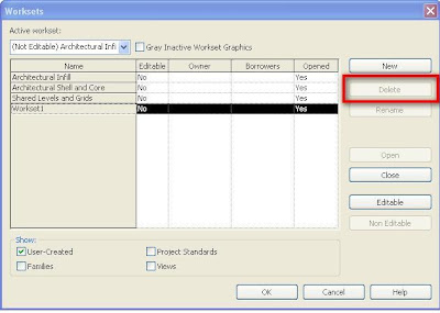
Select the offending workset and click "Delete." Note: there is no way to change the setting that is causing the issue. You have to move the geometry to a visible workset.


When you do this, you are given the option of deleting the objects on that workset or... cue drum roll... select which workset to move them to. Select the new workset from the drop down list. Now you can rename the new workset to match the old one and no one will be the wiser.


Where you aren't able to do this is if the offending workset is (or originated as and was renamed) Workset 1. When you select that workset "Delete" is greyed out. As a practice we rename the default Workset 1 to Coordination and only use it as a holding pen for "lost" items.


Here is another quick video to help explain. I apologize for going a little fast. Actually I just watched it and it is a little confusing since it isn't narrated. If you have questions, be sure to post them here. Sorry that there's still no sound. Quality microphones don't grown on trees. ;)

Monday, June 29, 2009

The Revit X-Files

The truth is out there... I think.

So this is a new category of posts here at Big Bad BIM. Reminiscent of Revit OpEd's Department of Unfair. This will be the repository for all the freaky,weird, off-the-wall Revit stuff that just drives me CRAZY!!!


I think Autodesk calls these "service requests." Ok, ok, I'll try to log those too.


First installment comes from our Mechanical Engineering department. One of our user's was trying to use the "Tag All Not Tagged" tool to tag all of the ceilings in a view. He just couldn't get it to work. He could tag them one at a time, but not all.


Wondering if it was something related to that particular project, I tried it in a view that was set to the Architetural discipline as opposed to the Mechanical discipline. Sure enough, no problem. I changed the view in question to an Architetual discipline. Tagged All Not Tagged and changed it back. Worked great. Work-around? You bet, but we have lots of those.

Back at my desk, I wanted to make sure I hadn't missed something. So I compared the element properties of a couple of views.Here are the results (notice in particular the "underlay orientation"):


Architectural Discipline:


Mechanical Discipline:


Note: the Mech view didn't default to "Plan" for the Underlay Orientation. I changed it. I CHANGED IT!!! You shouldn't be able to do that. That parameter allows you to underlay a ceiling plan in a plan view (so you can coordinate overhead information with your floor plan.) I don't think we were meant to access this in a ceiling plan.

Are these two conditions related. Is it a programming bug? Aliens that have it in for HVAC designers? Who knows, but it sure is weird (not to mention frustrating.)


Here a couple of ceiling related videos. First is a video that shows the workaround mentioned above. The second is a video that shows how to apply filters (powerful little buggers, those filters) that make "non-standard" ceiling heights really "pop," which really helps when coordinating information in the model.


Wednesday, June 24, 2009

A BIM filled week

It has been long week already, and it's only Wednesday!

Monday was the first meeting of the Madison MEP User's Group that I have attended. Being new to the area it was great to be invited. Thanks to Westphal Electric for hosting and thanks to Scott Brisk (Revit MEP blog) for facilitating (thanks for the invite Scott!!) There was no particular application affinity in this group, although it seemed to be weighted towards Autodesk products. This seems like a great group of folks and it's always nice to see what other BIM users are doing out there. Model to fabrication, and Model to total station "round tripping" are two topics that were mentioned a number of times (and probably deserve a follow up post.)

This morning, Ed Deal (AEC Building Technical Specialist for Autodesk) presented a seminar in two sessions. The first was titled Construction Documents and Beyond. The focus was on breaking out of the Construction Document (CD) trap. While Revit can produce 2D printed documents that rival anything ever produced in CAD (when set up well,) it is at heart a design tool and in it's soul is a BIM authoring tool. Needless to say, lots of ideas about verifying programming, quantifying design iterations and schematic analysis were presented. My kinda topics.

The second session was geared towards the MEP crowd ( it was nice to see faces from the Madison MEP User's Group again so soon.) The topic was analysis tools that leverage the Revit Model. Starting with a very schematic model (approx 45 mins of modeling) Ed analyzed various design iterations using the tools available natively in Revit, Green Building Studio, and Ecotect. Some of the things that Ed did I'm not sure you can even DO with CAD drawings (certainly not with the level of accuracy and in the same amount of time.) I'll try to post links to the White Papers referenced. Thanks ED!

Tomorrow we (Cogdell Spencer Erdman-Madison Office) host the Madison Revit Managers Group. So hopefully we will have some useful blog-fodder from that meeting as well.

In the next couple of weeks, expect posts about:

Ceilings (the videos are already on my YouTube Channel) note: would have posted about these earlier, but my laptop went 10 rounds with a small dog and lost it's "C" key. I just can't "see" posting about Ceilings without a "C." :P

An update to Plumbing "Fixture Unit" Flow. (Hint: I think we found a way to make it work.)

Is Revit faster than CAD? (a definitive answer...?)

etc etc.

If you don't see these soon, you need to get on here and nag me till they show up.

Thanks all,

E

Friday, June 12, 2009

"Family Type" Parameter in a Type Catalog Part 2

JING is great, but the .swf files are a pain to embed on Blogger.

Who's afraid of the Big Bad BIM? finally has a YouTube Channel. Hooray for technology.
The quality still isn't great. From Jing (freeware) through a trial .swf convereter (also free) to YouTube. I guess I will have to spring for Camtasia after all... Fathers day is coming... Hmmmmmmm.

I recommend viewing AT YouTube's site>Clicking the HD button for higher quality>and watching in full screen.


Wednesday, June 10, 2009

"Family Type" Parameter in a Type Catalog


They say that absence makes the heart grow fonder. Let's hope so fans. Of course I think the actual quote is "Absence makes the heart grow fonder... for someone closer." If that's the case, I hope my favorite Revit bloggers got a bump in readership. :)

In a comment on an earlier post, a reader asked if it is possible to drive Nested Families with a type catalog. In a subsequent email he issued a friendly challenge to prove that it can be done and show if a Yes/No parameter can also be controlled as well.

Nothing will get me blogging faster than a challenge. Thanks Matthijs.

What follows are links to a couple of quick video clips that I hope explain how it can be done.
(bonus: note that you can drive "instance" parameters with a Type Catalog)
Here is the Type Catalog. I always like to create and edit my type catalogs in Excel and then save to .csv format and change the extension to .txt. It's just easier for me.


As you can see in the second clip, I alternated each parameter value. Just make sure that you spell the "Family Type" parameter the way it appears in the value cell in the Family editor.
Oh, and the 0's and 1's? Binary, Baby! 0=No 1=Yes.

Good luck, and keep the challenges coming.

Wednesday, April 15, 2009

Revit MEP (Plumbing) Piping Flow: another second class citizen

Warning: What follows is a rant fest filled with WAY more information about MY ideas of how both plumbing design and Revit MEP work. Any deviation from reality on either subject can wholly be attributed to a 14 month old daughter, a pregnant wife and a looming Revit configuration deadline. Please excuse my definite lack of plumbing design knowledge. See one, do one, teach one, I always say.

Revit MEP is ALL about propagating information throughout the model.

Spaces can be assigned a required Air Flow value.
Air Terminals know what space they are in.
Spaces know how much Air Flow is coming from the Air Terminals it contains.
Duct connected to an air terminal knows how much air is flowing through it (based on what the terminal is providing to the room.)
Variable Speed Fans (VSF) know the SUM of the flow from all the terminals connected to it downstream (Revit is doing the math on the fly.)
And so on and so forth all the way back to the Roof Top Unit (RTU) that SUMS all the VSF (and therefore all the terminals) that are connected to it.

We can tag and schedule this information fairly easily. And, it's used in sizing calculations.

Sounds keen.

Enter Plumbing pipe systems. (Cue ominous musical score.)

On the surface they work similarly to HVAC duct systems. But any plumbing designer will tell you (you have to listen closely they probably won't repeat it) that flow through a plumbing systems is different than duct systems. It's even different than flow through hydronic, or process systems.

The difference is DIVERSITY. No we're not talking about multiculturalism. Simply put, a system that contains 1 watercloset (WC) (that's toilet to the rest of us) has a 100% chance that all WC will be flushed at exactly the same time. Therefore the system is designed to accommodate the flow of that WC. A system with 100 WC has about a 0% chance that ALL will be flushed at the same time (aside from High School pranks.) Plumbing designers use a diversity factor along with Fixture Units (FU) to determine the most likely (design) flow in their systems. FU are assigned to fixtures (WC, sinks, etc) by Authorities Having Jurisdiction (AHJ(why is it always a TLA(Three Letter Acronym?))) so they can vary by locale. In short the designer totals the FU on a system and applies the diversity factor (which they get from a table) for the number of actual fixtures and that tells them the flow they need and therefore the pipe size. Whew! (Did I really have a 3rd level parenthetical statement back at AHJ?)

Why does all this matter? Well, for one, Revit doesn't get to look at that diversity factor table when it's computing flow. I can't even imagine the math used to derive flow from FU without it. All in all Revit does a darn good job of computing that flow and reporting it out to us. Connect a bunch of sinks to a pipe that connects to a water heater and the pipes will total the FU (and the resultant flow) from however many it is actually connected to.

Now the rub. The pipe that connects to the equipment (water heater) reports it's FU and flow fine, but NEITHER THE FU OR THE FLOW propagates to the equipment. You can create family or shared parameters based on both FU and flow. However, when mapped to the same parameters on the family's connectors (similar to how you cause Air Flow to propagate through VSF) you receive NO report. And, it will not propagate upstream.

At least I can't get it to work (and I tried every combination of connector settings related to those two parameters.) After talking with an Autodesk rep, it came to my attention that Revit MEP wasn't designed to pass flow through equipment in plumbing systems (where flow is calculated from FU.) So that means, I can't schedule equipment (like water heaters or softeners) and have the schedule show the actual flow demand on the unit (based on the system it is connected to.)

A bug? Unforeseen functionality need? I think it's just that the Revit code jockeys took it the wrong way when they were told to work on the FU systems...

BTW, this has been logged as a functionality request to the development team. Here's to making plumbing flow as useful as it's first class cousins Air Flow and (hydronic) piping flow. :)

Friday, April 3, 2009

Trouble finding hidden elements in Revit? Use; Select by ID

This handy feature can really save you when you are trying to figure out what objects are causing issues in your project.


The other day I was trying to resolve some warnings related to switching a wall from one type to another that was not as wide in section. I wish that I had taken a screen shot of the warnings... there were 18 warnings (cannot be ignored) and 9 errors (Revit telling you that you should pay attention and see if what you just did was really what you meant to do.)
The project was fairly far along (actually CDs have been issued, but there is some clean up going on in the model.) Swapping walls at this stage can cause all sorts of issues.
In this case all of the warnings and errors were related to a ceiling. I created a new section and oriented a duplicated 3D view to it so that it encompassed the wall in question. I selected the ceiling in the warning tree and clicked the "Show" button but it wouldn't highlight in the view.
So, I wrote down the ID number (you can't copy/paste here, so you have to go old school.)

(I guess you could screen capture like I just did to get this image though.)
Now, go to "Tools" Drop-down menu>Element IDs>Select by ID
Enter the # into the dialog and now you can either use the "Show" button to highlight the element, or the "Select" button to grab the item and modify or delete it.
If you are trying to scout something that is deeply hidden in the model:
Duplicate the Default 3D view
Use the Select by ID feature
Use the "Isolate Element" command (click the eyeglasses) to hide everything else in the project.

Now you can activate the Scope Box for this view and crop out most of the model to get a better idea of where the elemnt is and what may be causing your issue.
Good Luck and Good Hunting.

Friday, March 27, 2009

The Key to Giving 100%

I don't really like to link to others Blogs. But you just can't argue with logic.

Tuesday, March 24, 2009

Autodesk 2010 Design and Engineering Software Product Line Now Available

YAY!!!

I hope you're on subscription and your copy is in the mail...

Follow the link to the full press release.

Thursday, March 12, 2009

Revit Type Catalog Tip

Type Catalogs are a great tool to drive parameters and to keep your project file size under control.

Some families (like structural wide-flange steel) have so many types that it is nice to only bring the types that you need into your project.


To create a Type Catalog, start a new session of Notepad or some other text editor (not Word though, the formatting will cause errors in the Catalog.)

The first line lays out all the parameters you want to control. In this example I only used one parameter, "Type Comments." I like this parameter alot. It's in every family and isn't used by anything else. By default it is blank (more on that in a minute,) but you can use it to tag custom ID information for that object.


The second line begins with the Type Name, then a comma (this is a comma separated value file.) Followed by the values for the parameters you are controlling, again separated by commas. We'll keep it simple here. I do want to mention though that when working with complex Type Catalogs, I like to import them in to Excel. That way they are separated by columns, instead of commas. Just save it out as a .csv, then change the extension to .txt and it will work fine.

The purpose of this post is NOT to go into too much depth about Type Catalogs. There are decent instructions on the basics of Type Catalogs in the Revit Help file and a slightly more in depth treatment in the Autodesk Family creation tutorials.

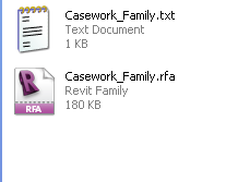
Name and save this file in the same folder as the family.


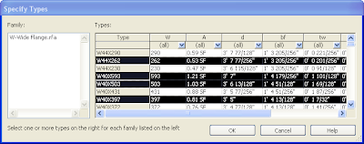
When you go to load the family, you get the dialog below. Control or Shift Click to select the types you want to load.
Click OK and you get...
This warning... Hmmmmmmm,
It actually does exist. It's just blank in the family. Since there is no data for the Type Catalog to override, Revit disregards that column of the catalog.
So, open the family. Place a default value in the parameter. It doesn't matter what it is, it will be overwritten by the catalog. Save it. And reload it into the project.
To show what we have, I created a quick tag that reads the Type Comments from the family.
To take on e step forward, create a new type in Family editor and load it into the project without saving or editing the Type Catalog. What value will the Tag show? The default...
In short, if you ever get the "Parameter doesn't exist in the Family" warning, check the family and make sure there is some sort of data in the field. It should work fine after that.

Tuesday, March 10, 2009

BIMwash, the new snake oil?

I'd like to take a moment and try and define a new term.

BIMwash.

A portmanteau (a word that contains two words and combines their meanings) of BIM (building information modeling) and whitewash ( a thin paint-like coating that washes away slowly in the rain.)


More and more projects are requiring BIM. Sometimes the Design firm is requiring BIM from the GC and subs. Sometimes the Owner is requiring that everyone use Building Information Modeling. This is GREAT! I mean this is what we have been preaching and railing about.

Here's the rub though. BIM has become a BUZZWORD. Not to the extent that "Green" has, but a buzzword still. Now that everyone's talking about this thing called BIM, folks are starting to sit up and take notice. Heck man, there's money to be made here. We can do this BIM thing. We already model in 3D (sorta.) This (insert any BIM authoring software) looks pretty similar. We can't get left behind on this. RFPs (requests for proposals) are coming in asking for BIM. Let's go!

So XYZ Design (or Engineering, Builders, etc etc.) gets a couple seats of software, spend some time learning how to use it, and get it set up so they can plot documents to their standards. Yahoooo, we're on the BIM-train. Let everyone know, WE DO BIM!
Whoa, hold the phone, Buster. What do you mean you "Do BIM?"

Ummm, we use "Brand A" Software and... produce a BIM.

What's your deliverable?

Duh, the industry standard 2D CD's. You can't get away from that. Oh, and we can show you exactly what your building looks like with renderings and walk-throughs.


So, since Contractors, Subs, Design firms, even Owners all have their own ideas of what is BIM, are they wrong?

Yeah, I think they are.

I'm not going to rant and rave about what is and isn't BIM. Just Google it, there is plenty of discussion. What I will say is, there are plenty of firms out there that have jumped "on board" and are "Doing the BIM."

Educate yourselves. Have a serious discussion at your firm. What is BIM to you?

Everyone wants to get something different out of this. The Designer wants to validate design and communicate design intent in a new and easy to understand way. The Contractor wants to query the model and take off accurate Quantity of Materials and investigate "Buildability," dealing with interferences early in the process. And the Owner wants a BIM that they can use throughout the lifecycle of the building. Let the world know what you do or exactly what you want. Define it internally before you put it out before the public.

If you are about to issue a RFP that requires BIM, do yourself a favor and SPELL IT OUT. Define exactly what you are looking for. That way you have a better chance of getting what you want. And please, if all you want is rendering and walkthroughs, say that. Don't even use the term BIM.

If you are a Design, Engineering, or Construction firm, know what your strong points are. Know what you can and cannot deliver. Don't oversell your abilities. It will only come back to bite you.

And if you're just using the term because "everyone is doing it," STOP.

Don't be a BIMwasher... it's all likely to wash away in the rain...

Open Source Building Information Model (BIM) Server (Round 2)

David Harrison linked to a post on his site that gives a far more in-depth discription of what a BIM Server is and how it could effect the industry. It can be found here.

I figured I would bring this to the front page.

Thanks Dave.

Monday, March 9, 2009

Open Source Building Information Model (BIM) Server

An interesting idea. I have to admit I found the site a little lacking in useful information. But then again, I have to plead complete ingnorance when it comes to servers.

Check it out here.

Wednesday, February 25, 2009

The power of Revit Subcategories

In my last post, I spoke about the importance of placing the symbolic line work of Pipe Fitting famlies on the correct subcategory (or in that case, that it was on the actual Family Category "Pipe Fitting.")


One of the ways to get the most control over the visibility of objects in Revit is to use various combinations of Graphic Overrides, View Templates and Filters that select objects by their "Family Category."

As mentioned before, every object in Revit belongs to a Family Category. Walls, Doors, Lighting Devices and Plumbing Fixtures are all Family Categories. So, if I want a view that displays Walls but hides Windows, I just check Walls and uncheck Windows. Simple enough.


However, what if I want to show Interior Doors but not Exterior Doors? Select an exterior door>right click> select all instances> and hide in view? Sure that would work, but it's time consuming. Especially if you have multiple types of exterior doors. Interior and Exterior Door Worksets? Maybe, but let's stay away from extensive lists of worksets. A filter? Sure, filter by something that all exterior doors have in common and is different from interior doors. Maybe you even have to add a parameter to doors to make it work. This has the advantage of being set as part of a view template and can be quickly applied to multiple views. All of the above are passable ways to turn on and off and change the graphics of different objects in Revit. But what if...


I wanted to control part of an object? Enter... Subcategories. You have probably dealt with them before. Say you want to turn off the elevation swing of doors in Elevation. Just uncheck that subcategory in the Visibility/Graphics Overrides Dialog of that view.


And the great thing about Subcategories is that you can great an infinite number of them, unlike Family Categories (where you're stuck with what Autodesk gives you.)


To apply these subcategories to different parts of your object, in the family editor you simply select the "part"(which can be a number of things, 3D Geometry, Lines, etc.)>open the part's element properties> and assign it to the appropriate subcategory (just use the drop down list.)


Now you have TONS more control over objects in Revit. We recently had a situation where we wanted to create a Plumbing Fixture family that was an in-wall rough-in. By making this a family (instead of just text in the view) we can tag it, and run piping to it. However, most views needed to hide the rough-in, but still show other Plumbing Fixtures. Sure we could have just selected it and hid it in the view, but we often do multiple instances of rough-ins and we wanted complete control of the family visibility in all views.


I'm sure by now you figured out that we created a rough-in subcategory and added the appropriate visibility/graphic overrides settings to our view templates.

Thursday, January 29, 2009

Broken Revit MEP pipe fittings

Part of my duties at Erdman is to QC the engineering content that is being created. Some of our content is being created in-house and we are outsourcing quite a bit as well. A number of the pipe fittings that we received from our content vendor arrived in this condition.
Centerline_Coarse
When the view’s detail was set above a “Coarse” level, the symbolic line that represents the pipe continues through the fitting. When set to Fine level the fitting displays correctly.
Centerline_Fine
What was causing this strange behavior? Categories (or maybe it’s subcategories.)
Every object in a Revit project belongs to a category. Walls, windows, floors, etc. are all categories. So are pipes, pipe fittings, etc. When you dig a little further, opening the pipe fitting inside the Family Editor, and looking at the object styles available, you will only find one category available. This makes sense, given that each object can only belong to one category. Notice however that there are SUBCATEGORIES under the category of the family. These are very powerful. I’ll write a post about using these later.
So, what does this have to do with our broken pipe fittings? Well, the model lines that display when the view in the project is set to medium or coarse were actually set to be one of the subcategories (Center line) of Pipe Fittings.
fitting_props
Once these were changed to “Pipe Fittings” the fitting behaved correctly.
So far, 6 out of 10 of the fittings we received from our vendor have this condition. With 100’s of families to QC, I am less than pleased.
In short, I recommend, when purchasing content from a 3rd party, make sure they know the product inside and out. These fittings (and other content we received ) were modeled beautifully. However, a 3D object is less than half what we are looking for when it comes to BIM.
I suppose I can forgive the error; there just aren’t that many people with tons of experience with Revit MEP. I just wish we had the staffing necessary to QC the content before so much was created.
Live and learn.
Next time, the power of SUBCATEGORIES…….!